As I wrote in an earlier post, I purchased and constructed wooden legs but an aluminum frame. Normally this would have been a problem but the manufacturer of the frame makes a shoulder hub with 4 large bolts while the leg fabricator makes his with 6 holes with T nuts. I did not notice this until I had finished putting the legs together and tried to attach them at the beginning. I put the problem on the back burner until today.
There was a lot of thinking, testing, thinking again that went into this. I did not want to make a mistake that I couldn't go back on. The shoulder hubs on the COM8 frame are turned 36 degrees for a three legged driving droid or at 0 degrees for a static droid (one that stands there and looks pretty). I assumed that someone that had metal legs would only have the 4 screw holes for the frame and that you would either screw them in with the legs straight up and down for a static droid or at that 36 degree mark for a three legged droid. But the legs still only had the 4 holes right? After a whole bunch of measuring and calculations, I figured that I could just drill two more holes in my legs in the 0 and 180 degree locations and I should be golden.
I found some T nuts the size of the bolts for the frame on McMaster-Carr and decided to make my hole line up properly. I used my Dremel to countersink the nut and some E6000 silicone and then JB Weld to hold the nuts in place. I also used some twisted nails (I don't know what they are really called :) to hold them into the wood. I am going to test these out soon and may decide to attempt to drill out the old nuts (they are a smaller diameter than the bolts) at the 90 and 270 degree locations and replace them with new T nuts for extra stability and hold. Don't want the legs falling off of my droid.
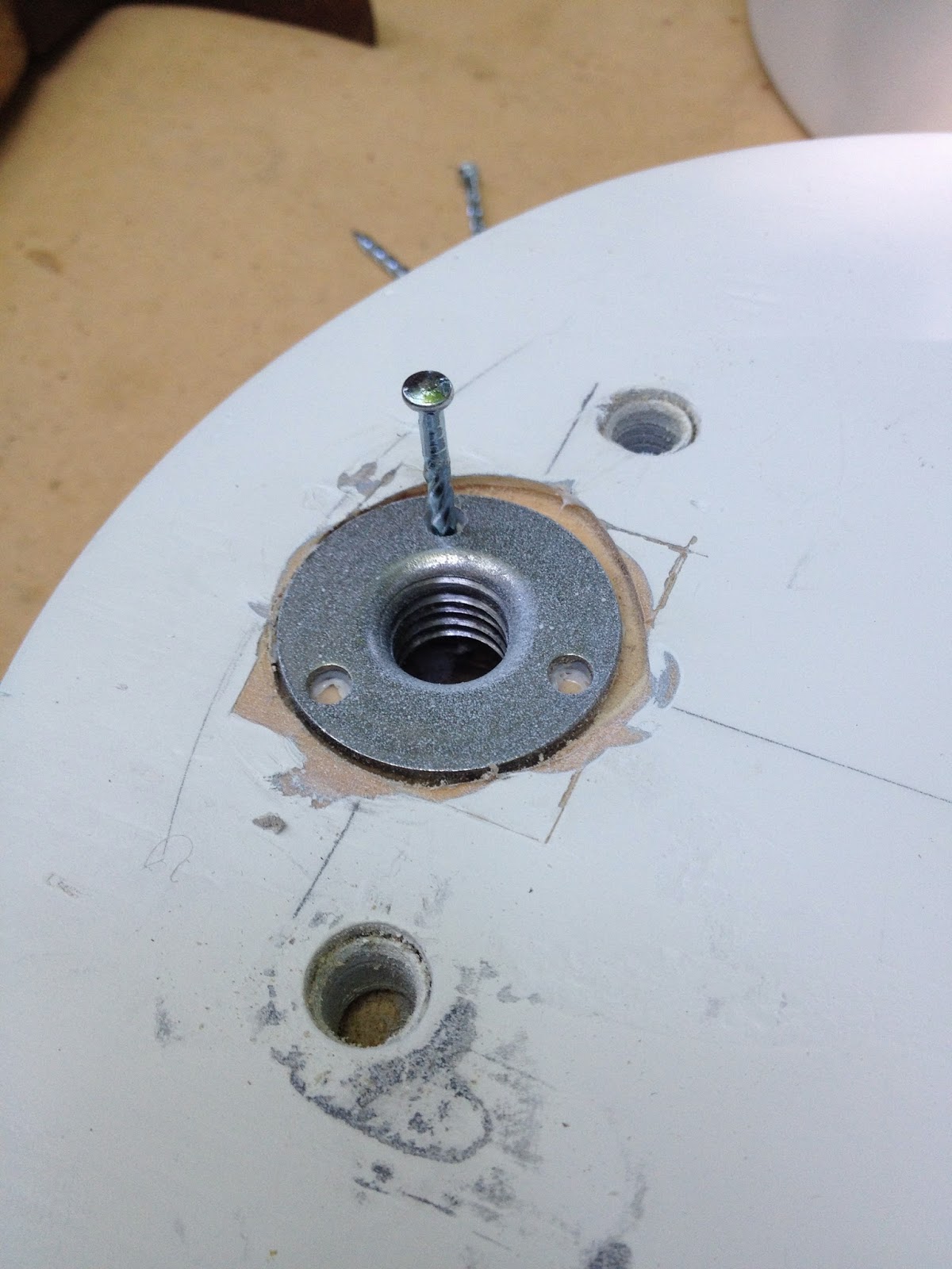 |
| Close up of the T nut and nail |
 |
| Locations of the new nuts and old holes |
The rest of today I spent finishing the details on the legs. Everything was painted, except for the booster hydraulics and under shoulder details, so I decided to put them together. First I painted the pieces that were not ready so I could add them at the end of the gluing stage. The horseshoes and shims went on with a bunch of E6000 clear silicone adhesive. No problem clamping those and getting them lined up fairly well. The shims or maybe the legs were not cut exactly right or maybe I sanded the legs a little too much, but no one is really going to notice except maybe another builder. The buttons and horseshoe hydraulics were simple to glue in as well, I didn't even bother with clamping those as they sit there perfectly and are pretty light.
The ankles were simple as well. I hammered on the aluminum ankle plates first and then glued down the chunky ankle piece (the big white piece to the left of the long red one in the picture below). Clamped that for 20 minutes. Then I came back and glued on the cylinders first and then pushed the wedge into place too fit. Finally, the cylinder holders were the last ankle piece to be placed.
The final piece to be put on the legs were the bane of this whole project so far. These single pieces have given me the most trouble, the most repaints and detail paints, and repaints again. And now they were about to almost give me a nervous breakdown as I glued them on. I'm referring to the booster covers (the big red thing in the middle with the silver details). First off, there are so many nooks and crannies on this piece that spray painting with equal coverage was very difficult and still didn't turn out the way I'd have liked. Then I was having an issue with the iodized paint reacting with the chrome paint that I was supped to put on the detail portions (I ended up just hand painting with the silver metal cast base coat and it looks fine). I also had to repaint these things twice because the red paint pooled in a couple of large key areas and looked like crap, very dissatisfied with these parts.
Gluing them down proved to be just as much of a hassle. There are no 90 degree angles on the top faces of this piece. Finding the correct placement for the piece was easy because of its size, but finding a way to clamp it down was another matter. Because the "legs" of the part are angle sloping from the inside (higher) to the outside (lower), when I put the clamps on it kept pushing the piece to one side or the other. Then when I thought I had the same amount of pressure on both clamps I noticed that the "legs" were both being forced toward the center line. Finally I decided to just clamp the head of the piece and forget the legs altogether. It worked out and the part is hopefully permanently adhered to the leg.
But that was not the end of the drama. The parts in the last picture, were to go in between the legs in the gap. Simple enough, especially because the square head of that piece fits perfectly just below the head of the booster covers. One small problem though, the base of the new piece is suppose to be placed just above the legs without touching them if the leg is laying down like you see in the pictures. I tried to stand up the leg to allow for these new hydraulics to dry but there was a different problem there. They are in two parts and one has a hole, which is deeper than it need to be, and the other has a stem to sit in there. The part started slipping down into the hole. When I laid the leg back down the part fell into the gap between the legs of the booster covers. I came up with a MacGyver style fix using only a paper clip. I bent the clip into a U shape with longer arms. I cradled the part in the U while the arms rested on the red booster cover, keeping the part floating where it was supposed to be. I left it there for two hours before removing the paper clip just for good measure and it worked beautifully. Woo hoo, the legs are finally done.
 |
| The almost finished legs |
 |
| Chroming the booster hydraulics |
 |
| Paperclip under hydraulic trip |
No comments:
Post a Comment